
MrCNC - part 1
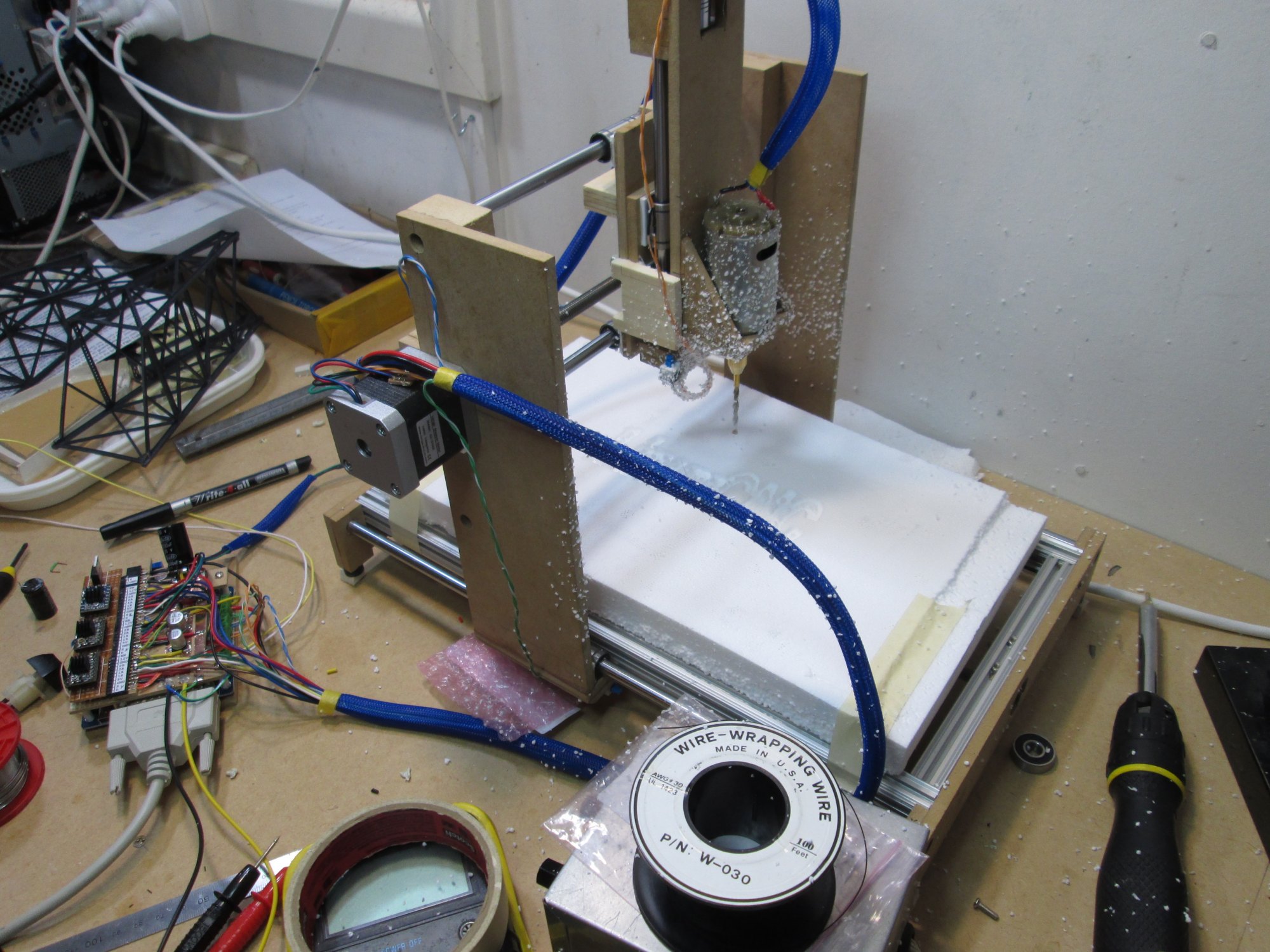
Today I present the latest project to come out of my workshop: a CNC machine! CNC stands for Computer Numeric Control, which is a fancy way of saying computer-controlled. A CNC machine has a rotating spindle that is movable in 3 dimensions and is able to carve, cut, and machine objects according to the input file on the computer.
Building it has taken most of the past month. An initial plan was roughed out on the computer and I started ordering bits online.
The first bit to be built was the bed of the machine. I made this out of Open Beam, which is aluminium extrusion, 15x15mm with built in slots to accept M3 nuts. This makes it easy to bolt the bits together, like some kind of giant Meccano set. The corners are chopped up T connectors and help square things up.
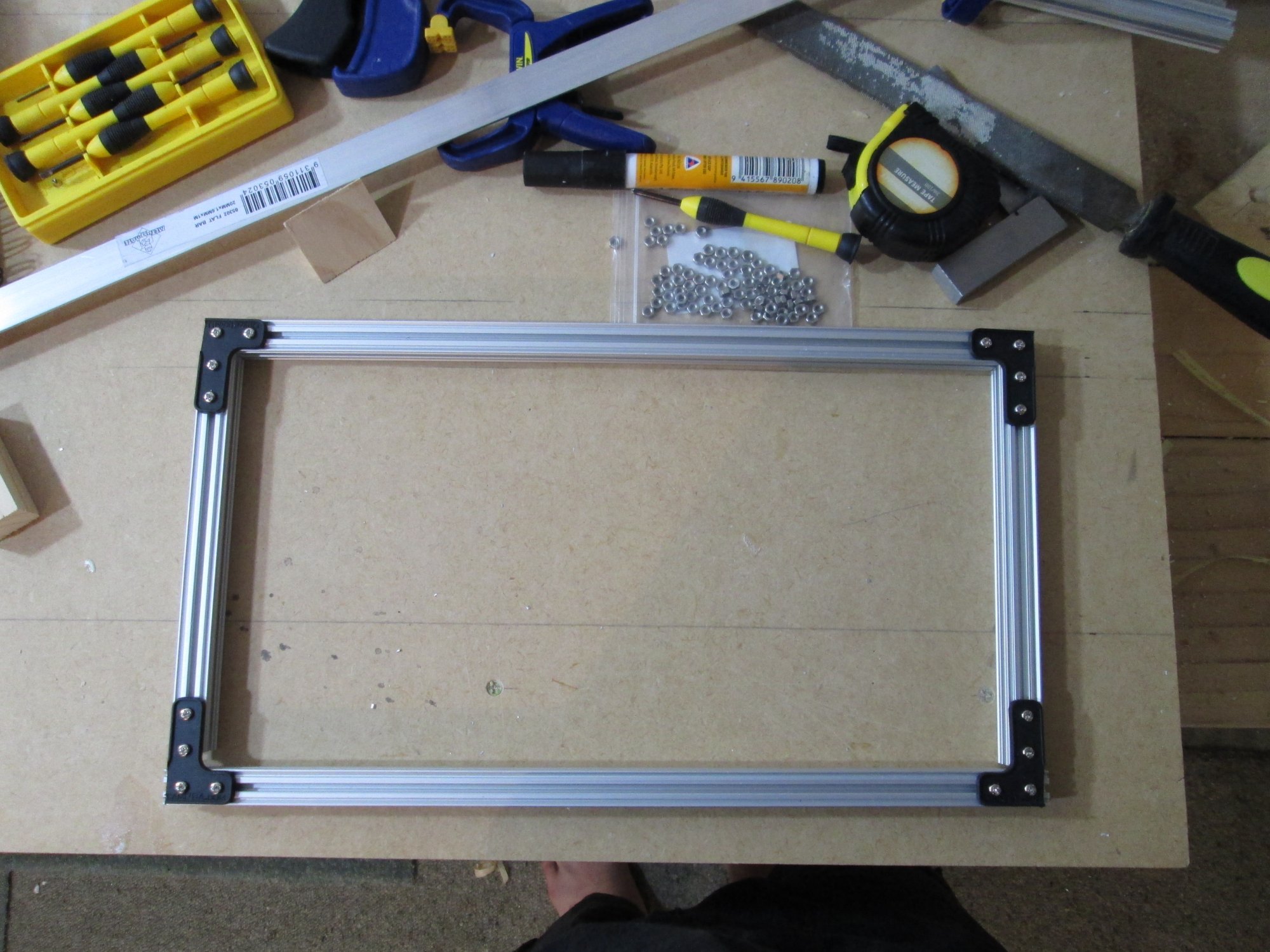
Ends for the bed were made out of 6mm MDF, which is good and regid, but not overly cumbersome to work with. I cut both ends as one, then stuck them together with double sided tape while I match-drilled them on my drillpress. This ensures that both ends have their holes in exactly the same location, helping keep everything nice and square.

The ends were mated to the bed and everything squared up. You can see my construction plans behind.
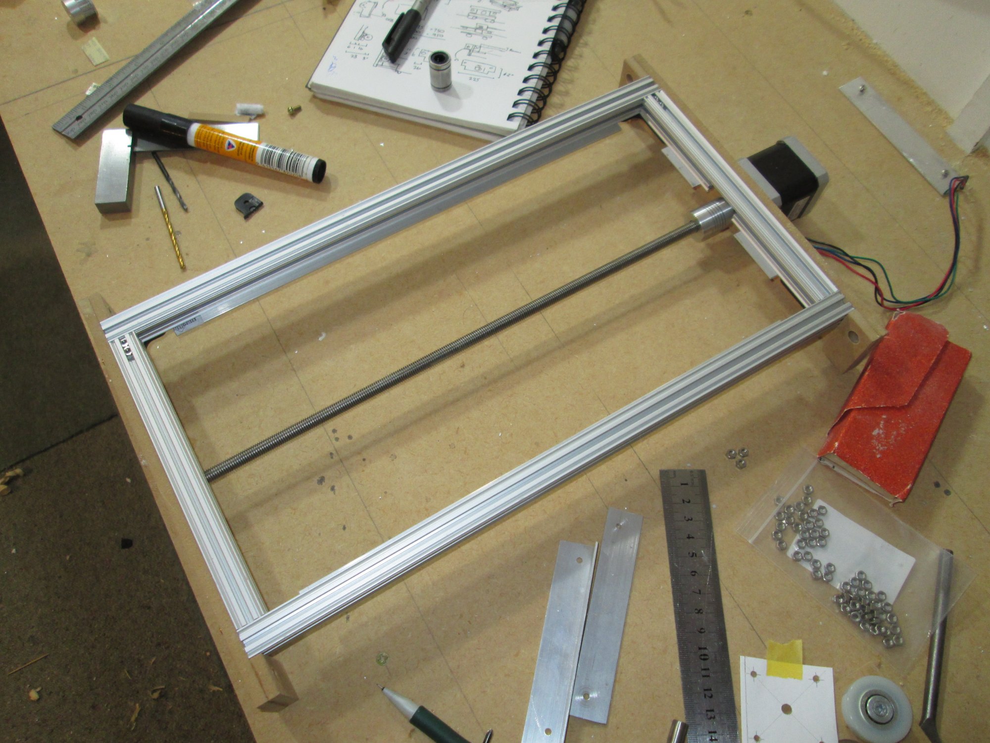
M8 stainless steel threaded rod is used to translate rotary motion into linear motion. Using some rather fancy flexible shaft couplings the M8 rod is mated to a stepper motor. Some heat shrink tube is used to increase the M8 rod to a full 8mm diameter and ensure a tight fit in the couplings. The shaft couplings are very nicely made, and dirt cheap from ebay.
With the bed mostly made I moved onto the Z axis. The Z axis moves up and down and carries the spindle. More MDF and 8mm match-drilled holes and it was starting to take shape.

The spindle mounting was of similar construction.

At this point I attempted to cut the smooth linear rod to length. I was being quite careful with it, not wanting to scratch it. However when I took my hacksaw to it, nothing happened. At all! After furiously sawing for a minute, all that had happened was the rod was slightly shinier where I had been cutting.
Some frantic confused Googling showed that I needed some more serious cutting gear. A trip to Mitre10 ensued and I emerged with an angle grinder and a pair of cutoff discs. I clamped everything up and took a shot. First cut was very slow, with lots of fireworks, but it did it. By the time I did my last cuts, I was only taking about 30s to get through the rod.
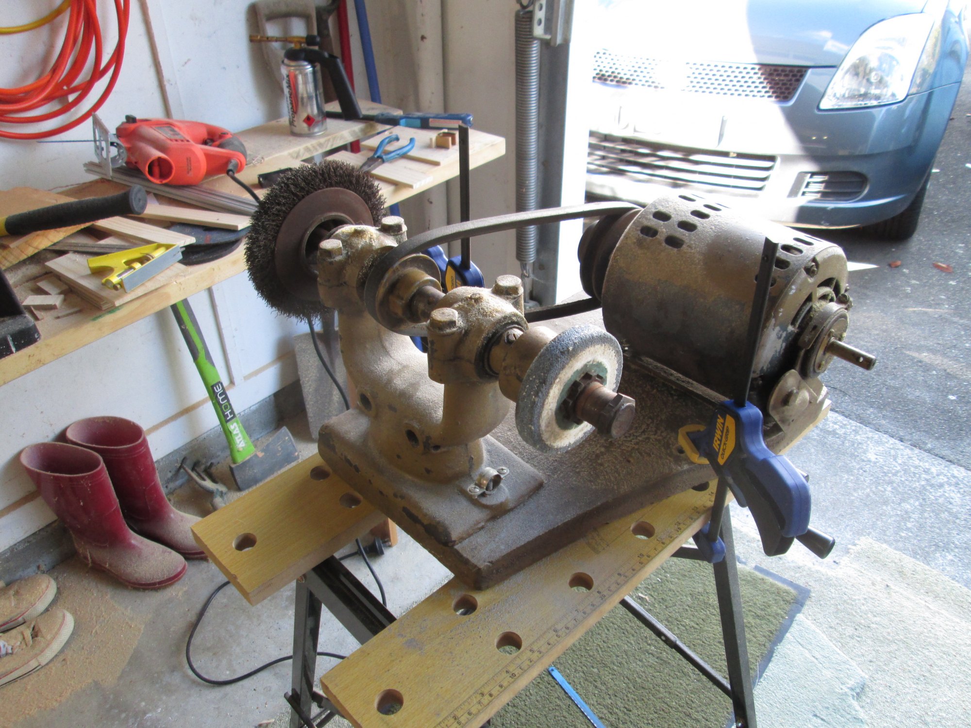
To clean up the cuts I switched to my trusty bench grinder, complete with finger-murdering belt. I tried mounting it to my work bench however that couples the bench grinder to the house, and the vibrations resonate through the entire building and it sounds like you're living inside a tank. So free-standing on my WorkMate works much better.
As I was assembling the Z axis I realised that moving just the spindle up and down would only give me about 40mm of clearance. After some head scratching I flipped the Z axis around and now I have 100+mm of clearance.
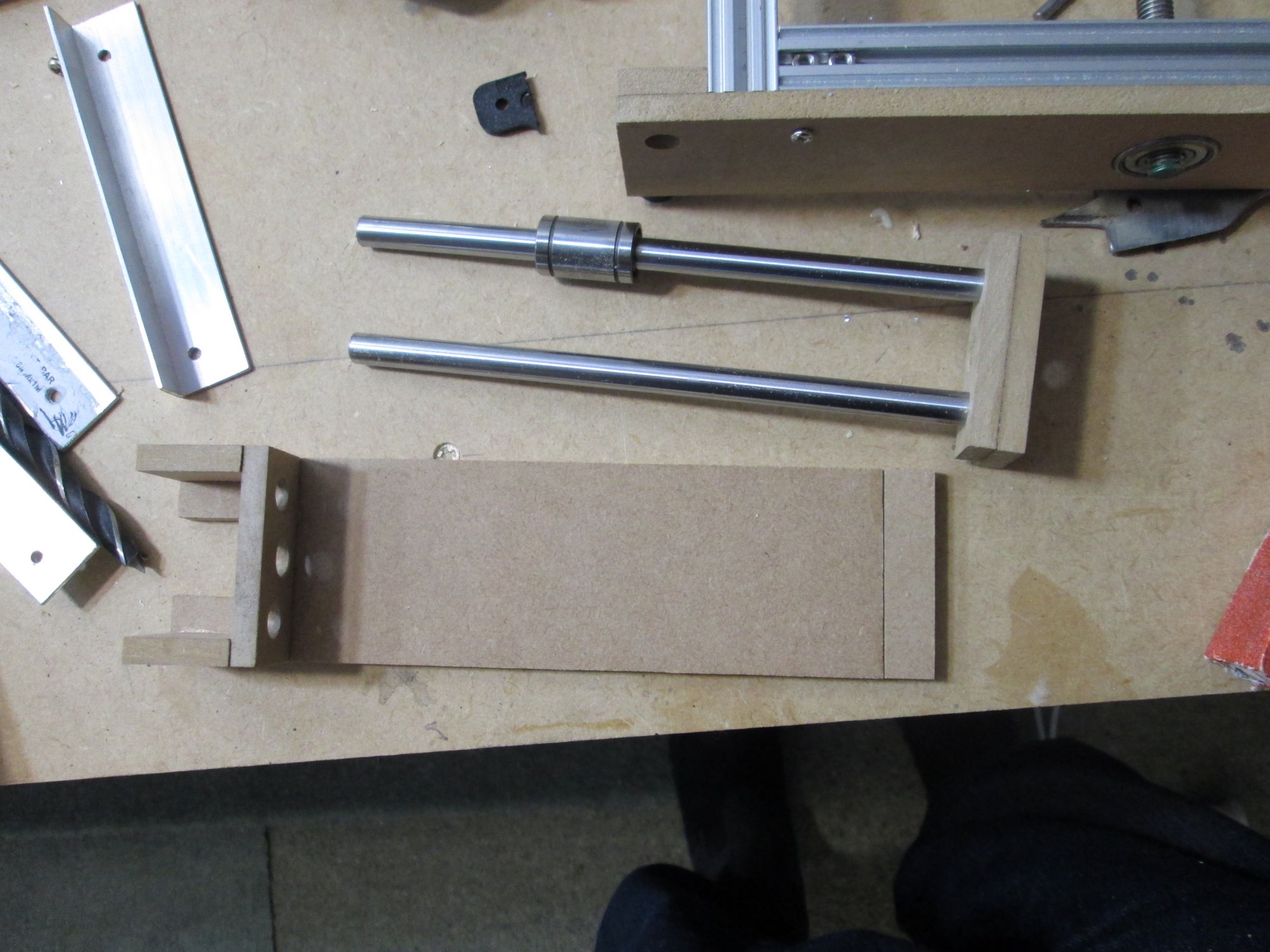
Just in time, my LM8UU linear bearings arrived in the mail. These are ball bearings that slide smoothly along a rod, helping ensure smooth motion.
One of the big challenges I faced was how to attach the bearings to the rest of the machine. At first I was going to cast up bearing holders, however I realised there was no way I would be able to make them square enough. Instead I made up some bearing holders out of styrene, with two parallel strips at exactly the right distance apart. I roughed up the outside of the bearings on my bench grinder and coated them in 5 minute epoxy adhesive. They then nestled nicely into the trough shaped styrene brackets I'd made up.

The top of each styrene pad is exactly the same distance off the linear rails.
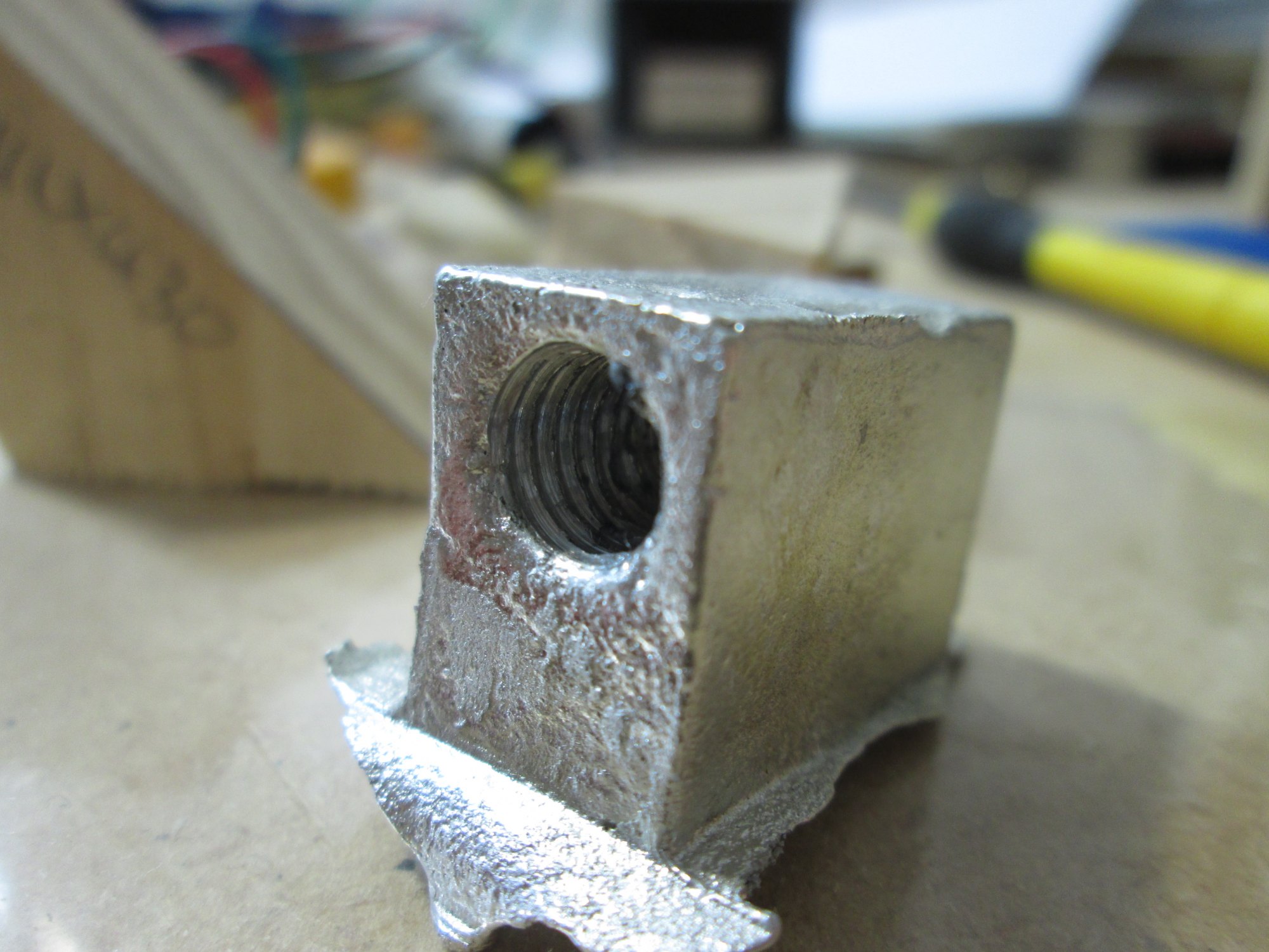
The other item I needed was a "bolt" to connect the threaded rod to the platforms. Now I could use a regular M8 nut, however they have a lot of slop as they aren't a precise fit. Instead I cast a white metal block around the rod, ensuring a very tight fit. To ensure it wasn't too tight, I coated the rod in a thing film of PVA glue. This adds just enough tolerance to ensure I can still rotate the rod afterwards.
I cast the block around the rod and then as soon as possible chucked it up in my drill and extracted the rod. Running it in and out a dozen times helps machine the inside of the bearing block to be nice and smooth.
I cleaned up the casting and then used more 5 minute epoxy to attach the spindle mount.
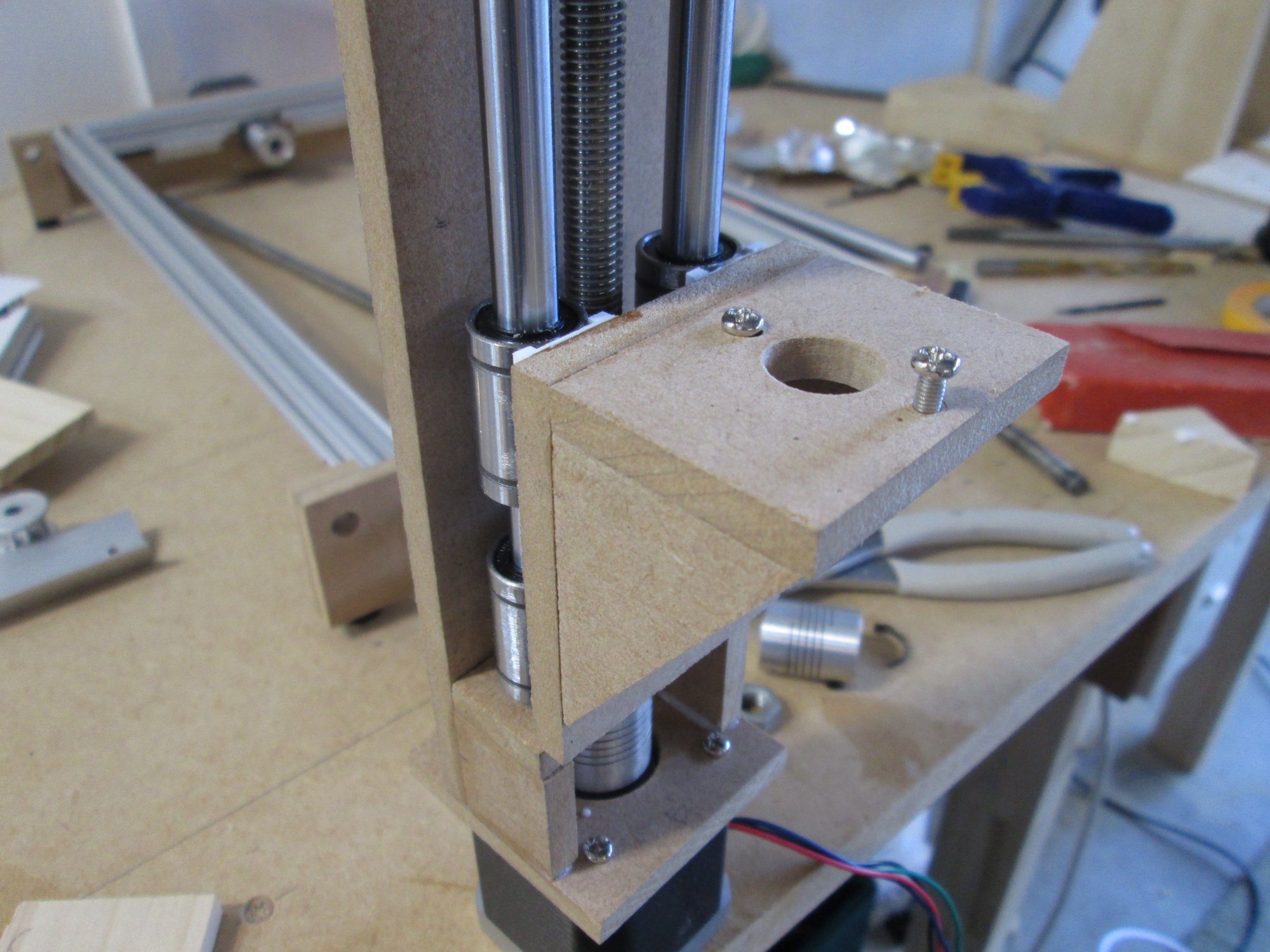
The Z axis (seen here upside down) is now mostly complete. Stay tuned for part 2.
Leave a comment?